Introduction
The Model Production and Delivery Table (MPDT) is an essential tool for managing a BIM project.
An MPDT defines who produces what, when and to what level of detail. An MPDT is such an essential part of a BIM project that producing a table is a requirement of the CIC BIM Protocol.
Producing a fully detailed MPDT is not a simple process and will require an investment in time, especially the first couple of times that you do it.
There are 4 key areas to the table
- An overview of the different project models
- Identifying the project stages

- The elements of the project are listed for each designer

- The amount of detail for each element for each designer is defined.

Before I provide more detail on the purpose of each section and how each should be completed. I will explain how and why the table used in this example has evolved from earlier versions.
The CIC BIM Protocol example MPDT defines design processes rather than actual elements of the project. For example the table used below lists out the specific build elements of a project (from a standard classification) such as external window systems and electrical heating systems (both taken from the Uniclass 2015 systems table). Whereas, as the CIC table lists generic items such as structural performance, fire strategy and MEP systems (as one item). The MPDT is used to ensure that design is developed sufficiently (and also not over developed) at each project stage. Therefore, it is logical that the table includes project specific items rather than generic design processes.
The table in this example also differs from other tables by having the elements listed by responsible designers, rather than listing all the elements and identifying the responsible designer at each project stage. Both formats have benefits and you may decide to alter the table for your own specific requirements. Through the use of MPDTs it became clear that the table requires both level of detail (LOD) and level of information (LOI) identified at each stage. And that the organisation responsible for providing the LOD (the graphical geometry) at a stage may not be the same as that providing the LOI (the information).
If we take floor finishes as an example. An architect will provide LOD for a floor finish and this may remain the responsibility of the architect through to handover. However, the data, which could be used by FM in a CAFM system, associated with the floor finish may be provided by the flooring subcontractor.
Producing a Table
Overview of the different project models
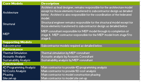
This section is designed to list out all the different models required for a specific project and provide a summary of what is expected and who is responsible.
Most projects will require architectural, structural and MEP models. However, depending upon the complexity and individual project requirements many other models and model uses may be needed. Some of these will be led by the client, but many will be necessitated by the needs (and deliverables) of a project. For example to achieve the required building thermal performance a thermal simulation may be required.
Construction simulations from 4D programming through to site setup and logistics would not normally be a contract requirement. Although, it’s useful for the design team to understand if a contractor may require the use of project models for construction simulations as the development of the models may be different for such uses.
Identifying project stages
An Employer’s Information Requirement (EIR) and subsequent BIM Execution Plan (BEP) will require the project stages to be clearly defined. Project stages usually follow those from either the PAS 1192-2 process map, the RIBA Plan of Work 2013 or the CIC BIM Protocol. All three are similar but have subtly different terms for the stages and in the case of the RIBA Plan of Works 2013 an additional 0 stage for strategy.
The table also includes the option of providing the planned date for closure of each stage. Which just provides a visual reminder of upcoming deadlines.
Project Elements and Responsibilities
This section requires that the elements or physical items that will be part pf a completed project are selected from standardised tables and listed against each responsible designer.
There are various classifications that can be used for this purpose such as Omniclass, Uniclass 2 and Uniclass 2015. We have where possible selected Uniclass 2015 as our classification of choice and this example refers to Uniclass 2015 systems table.
At the early stages of a project it’s not unusual for a project to have only an outline definition. However, all know elements should be selected from the classification tables and added to the MPDT.
Uniclass 2015 is setup in a way that elemental descriptions are hierarchical becoming increasingly specific and defined. The early stages of a MPDT for a project will usually start with the higher level items such as:
| Ss_25_30_20 | Door, shutter and hatch systems |
| Ss_25_30_95 | Window systems |
| Ss_25_45_88 | Tiling systems |
Rather than immediately going into specific definitions for each of the above such as:
| Ss_25_30_20 | Door, shutter and hatch systems |
| Ss_25_30_20_25 | Doorset systems |
| Ss_25_30_95 | Window systems |
| Ss_25_30_95_26 | External window systems |
| Ss_25_45_88 | Tiling systems |
| Ss_25_45_88_88 | Terrazzo walling tiling systems |
In this example table each project element is listed below each designer responsible for producing model information.
This does result in many of the entries being added more than once, for example where a subcontractor with design responsibility provides detailed information for the technical design. But, it makes it easier for each designer to clearly see their responsibilities.
Completing the Table with LOD and LOI
We are now at the final task for the completion of the table, providing clarity over the LOD and LOI required at each project stage.
The table used in this example provides separate requirements for LOD and LOI at each stage, as this provides additional clarity over the requirements.
LOD and LOI define the complexity within a model. Each project will require clear definitions of what is expected in the way of LOD and LOI, the definitions will be provided within the project EIR and BEP. If you are starting out on your BIM journey it’s a good idea to use established definitions such as those within PAS1192-2 or the BIMForum LOD specification. However, it’s not unusual to alter the standard definitions to provide a better fit for specific projects. But, any adjustments to standard definitions should be made really clear, to ensure that designers do not assume the default requirements.
It’s now a matter of completing the table for each designer to list out the LOD and LOI required at each project stage. This is not a simple task and it should not be attempted in its entirety at the early stages of a project. Instead the table should evolve and be refined as more project information becomes available. There are many factors that will alter the information within the table such as:
- Procurement routes (design and build, traditional, 2-stage, novated designers etc)
- Programme, as the programme develops the timing of the release of information may need to be altered
- Specialist Designers, what specialists are needed and when information is required
Using the Table
One of the main goals of BIM is to encourage and enhance collaboration between stakeholders. As with all of the key BIM control documents, these should be produced in collaboration with those required to deliver the information. This will ensure that the requirements are achievable, they are seen as a common goal and stakeholders understand the impact of providing information on other designers.
The table should be monitored regularly with any updates made available to the wider team.
Where dates are not achieved (or ideally risks of not achieving the dates are flagged in advance), the reasons can be investigated and understood leading to the development of mitigation measures.
I hope that the above information has provided an insight into the importance of the MPDT for all BIM projects and a route to developing a table.
If you have any helpful comments or require more information please let me know.
![]()
Contents